

_2d2230.png)
_5a42ce.png)
All Activity
Today
-
mostafamagdy joined the community
Last week
-
kylemckinlay joined the community
-
This will mean they cant sideload the Police response malarkey on their adverts
-
-
Your not allowed to talk about your employees like that anymore
-
Alfster23 joined the community
-
Relaxing
-
Locksmith Cardiff - Call City Locksmiths Cardiff for New Locks, Lock Repairs & Lock Outs. Experienced, friendly, 5* local locksmith for all Cardiff areas.
-
City Locksmiths Card joined the community
-
Hi all, I'm currently mapping out a project for a corporate client with their headquarters here and three manufacturing/logistics hubs across different countries in Europe and Asia. They want a unified system where a manager can issue an access credential (RFID or mobile token) at HQ, and have it immediately active across all sites. My concern is the global database synchronization lag and how local controllers handle offline authentication drift if the WAN link drops mid-sync. For those who have deployed large-scale, cross-border access control: Do you rely on a heavy local edge database at each site that syncs periodically, or are you pushing for full cloud-managed controllers that talk directly to a centralized server? How do you pitch the balance between "Instant Sync" and "Local Survivability" to an IT department that is paranoid about bandwidth consumption and data compliance (like GDPR)? Would love to know what kind of network architecture or hardware logic you've seen hold up best for cross-continental deployments.
Earlier
-
just how good is rushless technology ?
-
Recently bought a new tool Makes me so calm using that tech

-
-
sid101 joined the community
-
Are you sure its the panel battery? Where did you purchase the replacement battery, if its been sitting on a shelf for years it will be as flat as the one you replaced it with. How old was the original battery? Anything over four years could have been slowly killing the charging circuit? It could be a resettable fuse on the CPU so as Happy says restart the panel and powering up mains first followed by battery, if that doesnt fix it check the charging circuit next.
-
-
Dear all, I have a battery fault on my Texecom Premier Elite 48. I have replaced the battery with a correct new one but i am unable to clear the fault, either as a master user or by using the engineering code. Any suggests on what to try next? I’m thinking of backup up the system and then doing a default reset.
-
Sean62 joined the community
-
Hi John
-
Hiya John, Sounds rather err hardcore ?
-
Welcome John
-
Hi I'm John, I recently joined my present company Core to build up and diversify the business outlets, my background is M&E, Fire & security and data infrastructures. My reason for being on here alongside of obtaining and giving where possible information to assist the community, I have been in the industry for many years working for manufacturers, wholesalers and installers, having had my own business that covered most sectors of trades. Core who I am now with are looking to grow, and that is my task, so other than information giving and receiving, I'm looking for individuals and companies that would be interested in partnering with Core, I am currently working on two public tenders, which we need competent people / business to cover if successful, we as a business are also happy to assist anyone we can if they need extra staff or special assistance on things like data/fibre infrastructures. If anyone is interested in getting in touch, please do. Thank you for your time. John
-
JohnB - Core joined the community
-
fozzy joined the community
-
XXKK Crypto Exchange joined the community
-
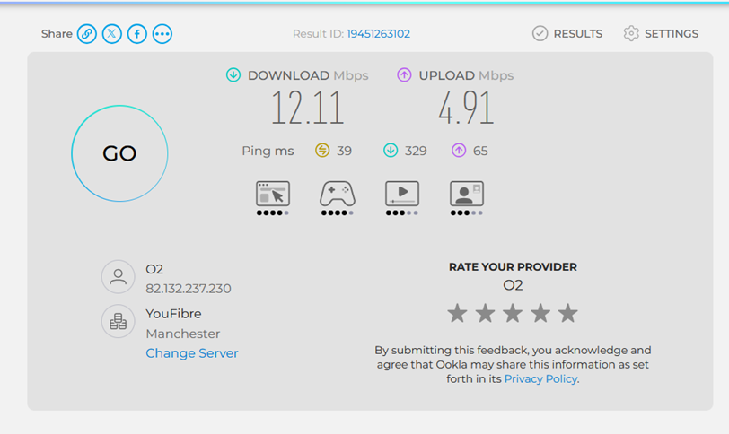
same thing, different sim
-
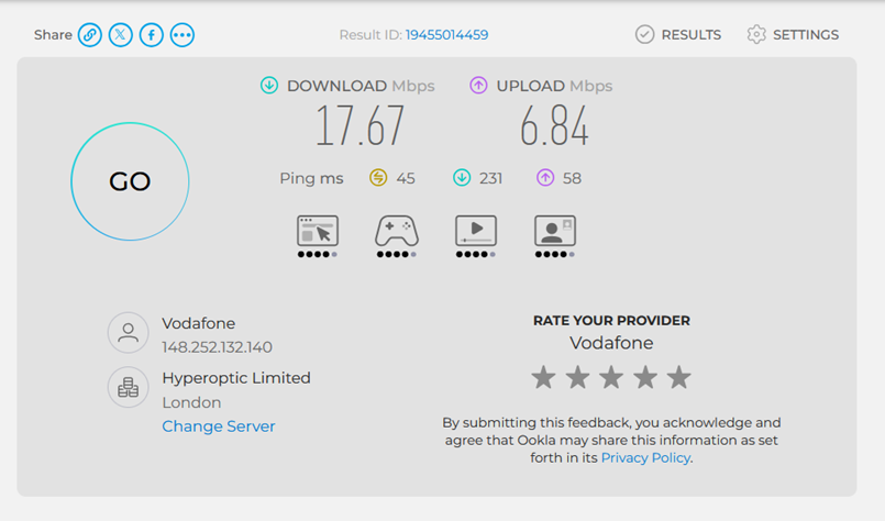
I've £50 4g sim router for a project which chucked on the floor, I wanged my cheapo giffgaff sim into It failed to detect so I turned it off, when it was turn back on, it auto configured Numbers ain't brilliant but will be good enough to fire emails off a laptop...
-
al-yeti started following Pyronix - reliability issues?
-
Lol
-
dont use it but is the wifi 2.4Ghz. You may need to enable a seperate non 5Ghz access point. Can usually be set in the router. What BB / router is it. Sky and EE can be a pain
-
poss router stopping you try fixed IP address on the enforcer and open the ports required on the router 443 25000 25010 top of my head most admit couple of my jobs ive fitted a LAN card and used them home switches to route the network to the panel
-
Probably never, I've only 2 x 10270 & a hub. Not really sure if I like them
-
When is the hub or q70 going in
-
I've an Orisec CP-20 in my house, wired bell, speaker & 4 pirs The wireless keypad is shite, the wireless contact on the front has a pyronix magnet as the orisec one is shite. The app is shite, the udl software is also shite
-
Am I the only one finding Pyronix gear becoming more and more unreliable? I constantly seem to be having issues with them at the minute, particularly with the WiFi connectivity on Enforcer panels/HomeControl2.0 app. I've currently got yet another v11 WiFi issue. The panel says I'm connected to the internet, but pyronixcloud.com and HC2.0 say I'm not. This one's only been in 5 months from new - and that was to replace one that was faulty from the factory... I really am tempted to just switch everything to Orisec. The only reason I haven't yet is out of habit, but there's no point staying with Pyronix with the high level of issues I'm having...


Who's Online (See full list)
Member Statistics
- 52,390 Total Members
- 1,932 Most Online
-
mostafamagdy Newest Member ·
Forum Statistics
- Total Topics 33.6k
- Total Posts 448.5k