Eugene's DIY Den
-
Posts
129 -
Joined
-
Last visited
-
Days Won
1
Content Type
Profiles
Forums
Events
Downloads
Gallery
Blogs
Everything posted by Eugene's DIY Den
-

Circuitry of Alarm Panel Outputs and Inputs
Eugene's DIY Den replied to Eugene's DIY Den's topic in !!..DIY Installers..!!
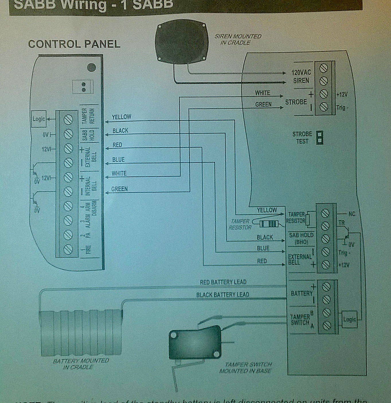
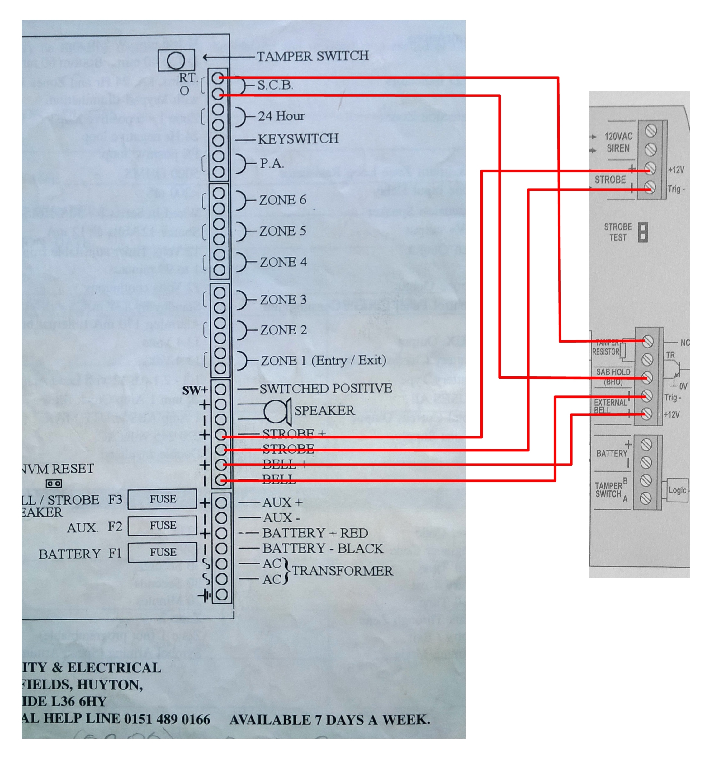
Yes, I would have thought that and pull up to 5v is at the point where NC is marked on the sounder. Then tamper return monitors voltage on the collector of the transistor which goes high or low depending on how the logic is setup. This photo (sorry about the quality) shows how they recommend connecting another panel. It seems to show tamper return connecting to the top screw terminal in the block, rather than the next one down. Maybe it's an error. I'll contact them tomorrow
-
Circuitry of Alarm Panel Outputs and Inputs
Eugene's DIY Den replied to Eugene's DIY Den's topic in !!..DIY Installers..!!
Can't seem to edit original post (is this not possible once a period of time has elapsed?). Panel is a ZX6, not an SX6. -
Ok, so I'm a bit confused about how the internal circuitry works for zone o/ps, switched negative o/ps and tamper o/ps. Terminology and o/p descriptions vary a bit on different panels and sounders, so I'm trying to get my head around it. 1) Bell/strobe switched negative - Is this o/p on a panel just an open collector transistor whose collector is pulled low when the base is driven, providing a ground for the strobe and sounder? 2) Zone inputs - Is one leg of the input connected high via a pull up resistor to the 5v supply, and the other leg tied to ground? When contacts are closed, voltage i/p is pulled low, then goes high when a contact opens 3) SCB0 and tamper return - Is SCB0 a permanent, nonn-switched 0 volt supply for powering a sounder? On some panels this is hard wired to tamper feed which is sort of a misnomer because it's a feed of 0 volts, rather than positive voltage.. Is tamper return a 5 volt o/p pulled high by a resistor internally or a fixed 5 volt supply? I'm trying to wire up an old A1 security and Electrical Advantage SX6 panel to a new HKC SABB sounder. This is the way I think the connections should be made.