Grego
Member-
Posts
54 -
Joined
-
Last visited
Content Type
Profiles
Forums
Events
Downloads
Gallery
Blogs
Everything posted by Grego
-
Thanks, much appreciated. Re compromised fob, I was given a bunch of fob's by an awesome bloke... so I can always program another one ? Thank you. Yes, I had looked at that. I am one of those people that has a keypad phobia and feels more at home with the GUI. Sad I know ? But I will give the keypad a go and see what happens.
-
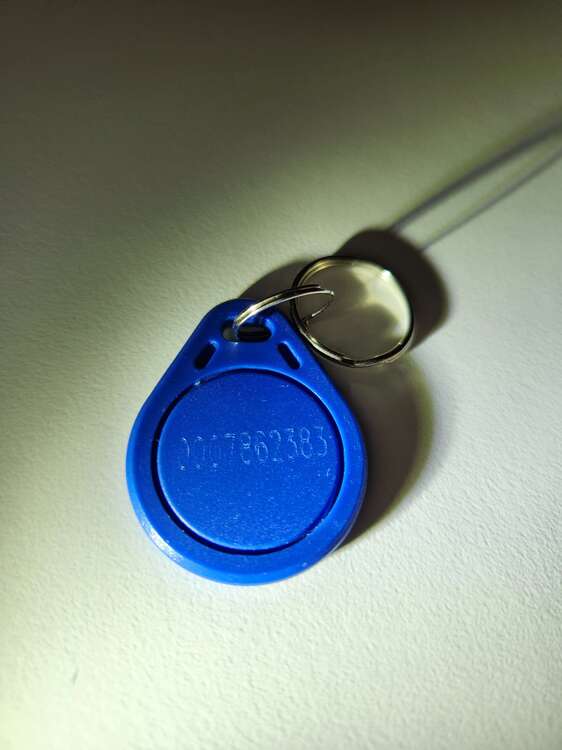
I have successfully installed my FX100+ system, and have a Mk7 prox pad which I'd like to use with fobs. I have read the manual and am a little bit confused on the setup. Here's what the setup looks like in the RSS software. I am a little unsure on a few areas. Under access control, which Menu Option would I choose? In the manual entry (below) it appears to say that when a user is using a fob they shouldn't have a PIN? I am unsure if I have placed the fob tag number in the correct location? Here's the fob I am trying to get working... As this is my first fob setup I have no doubt I am missing something simple. Appreciate any feedback.
-
Thanks Stuart. I'll leave in on 2... which makes it easier for my wife, and easier for me ?
-
Below from the manual... level 2 does exactly what is required - set and unset. Anything else I use a manager code.
-
I ended up changing the level (42.1.User code.2) for the user from 3 to 2 and the issue has gone away.
-
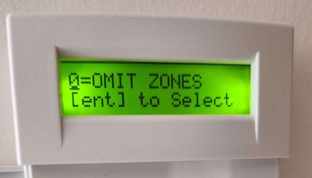
The system does set and unset, it just gives that message when unset. Occasionally we also see a message BOOT-UP, but the OMIT ZONES happens each time the system is unset.
-
Recently completed install of a Honeywell FX100+ system. Everything has gone reasonable well, thanks in a large part to feedback from the experts on this forum. When arriving home and un-setting the system, my wife follows the usual enter PIN and press ENT. Upon pressing ENT my wife sees the message below on the keypad. Is there a way to stop this message from appearing? Want to make my wife's experience really straight forward.
-
Give me suggestions and I can go from there.
-
Turns out I had the Program Outputs Polarity (53.3) the wrong way around, it needed positive polarity and not negative. I also set Mode 53.2 to LATCH, which I assume is the default setting. So the siren appears to be working, both in bell test and a full set test. I am planning on replacing the external siren/strobe... so perhaps the professionals on here could recommend a suitable domestic siren/strobe.
-
Did a walk test, and a full set test, and the external siren/strobe didn't fire? So I figure there's something I need to turn on for the opt ports to work?
-
Honeywell Galaxy Flex 100+ Exit Engineer Mode Issue
Grego replied to Grego's topic in !!..DIY Installers..!!
Thanks for the tips on bus devices and power down Stuart... much appreciated. -
Have completed all the wiring and programming following the Galaxy Flex Installer Manual. All rio's and zones appear to be working. Did a full set test, which seemed to work ok. Upon reentering the home and doing an unset the following message came up on the keypad... Not sure if that is an issue? Was surprised to see the message? Pressed esc to get back to the standard banner. Also wanted to ask... is there any suggestions on doing a realistic intruder test (opening a door that is set as intruder) to see if the alarm activates? I want to try and do a test without the external siren/bell going off (neighbours might not like it). Mind you, I am thinking I do want to be sure the bell and strobe actually work.
-
Honeywell Galaxy Flex 100+ Exit Engineer Mode Issue
Grego replied to Grego's topic in !!..DIY Installers..!!
End up going into engineer mode and then exited which checks the tampers and modules, it found the missing keypad and prompted me to press * to remove the two associated items. Looks good now, no issues. -
Honeywell Galaxy Flex 100+ Exit Engineer Mode Issue
Grego replied to Grego's topic in !!..DIY Installers..!!
Yes, you are correct. I temporarily attached a spare MK7 prox pad I had, and the system appears to be looking for it. I'll need to work out how to remove it? -
Honeywell Galaxy Flex 100+ Exit Engineer Mode Issue
Grego replied to Grego's topic in !!..DIY Installers..!!
Hi James. I ended up following THIS video which helped me at the tag correctly. Seems to be ok for now. I will reboot the panel later today and see what happens. -
Honeywell Galaxy Flex 100+ Exit Engineer Mode Issue
Grego replied to Grego's topic in !!..DIY Installers..!!
It is possible this issue may be related to a prox tag I attempted to add to my user code. I am seeing the following error codes on the keypad... Missing Key 11 Missing Max 11 I've read a few posts in here and have come up empty. My first attempt at a prox tag... so anything to point me in the right direction appreciated. -
I've done several trials, and here's what I've found. I wired as per the picture below... And configured the zone as 0ohm N/C and the chime now works when the door is opened. So, it might be working, I am not sure? This config is the only trial that resulted in the chime when the door is opened.
-
As an FYI... I wired a single zone as below... And set the FX100+ for just that zone to be 1K N/O (EOL) and it might be working? But I want to do some testing to be sure. My old system would tell me when a zone was open or closed, but I haven't figured out how to get that working on the FX100+ yet.
-
So when the door is closed the the reed is closed. As in the magnet causes the reed to be closed. So if the magnet is not there then the reed is open.
-
Installing a new FX100+ with a MK7 proxpad, and have come across the same issue outlined in this POST which describes... I enter the engineer code and press ESC and it checks for tampers and comes up with 1 Mod tamper which when viewed is Keypad 011. I followed the suggestion of holding down the tamper button and trying to exit engineer mode, but the same fault remains? Could this be a faulty keypad? The keypad is set to ID 0 not sure if that matters in this case?
-
Yep... completely agree. I figured it was bad option 1 or bad option 2 ? Appreciate your thinking.
-
Hi James... yes, it's a rubbish solution... but I figure having something is better than nothing. In your view, is one of the diagrams above better than the other... or both the same?
-
Thanks for the update. Yes, you are absolutely correct. Gaining access to the reed switches isn't an option right now (future plans to replace), so the best I can come up with might be below... Or I could use the wiring below... Obviously neither is ideal... but for now perhaps the only option?
-
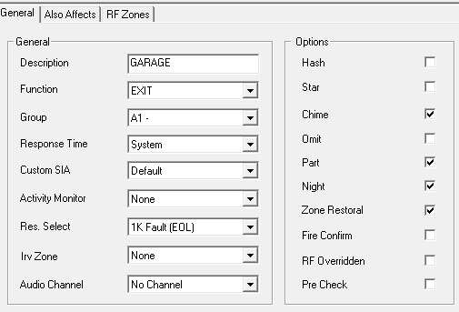
Hi Stuart. The picture below is how I have configured the PIR's as per sixwheeledbeast advised in an earlier post. So to confirm, are you saying to leave as the default 'double balanced 1k/1k' for the PIR's? Just an FYI, the PIR's appear to be working. The reed switches on the doors and windows appear not to be working. The wiring of the doors are a reed switch per door, and a 1k resistor at the 0V end. Picture below... Below picture shows the area I have been tweaking the config... but haven't found a solution yet. Any suggestions on zone config or resistance greatly appreciated.
-
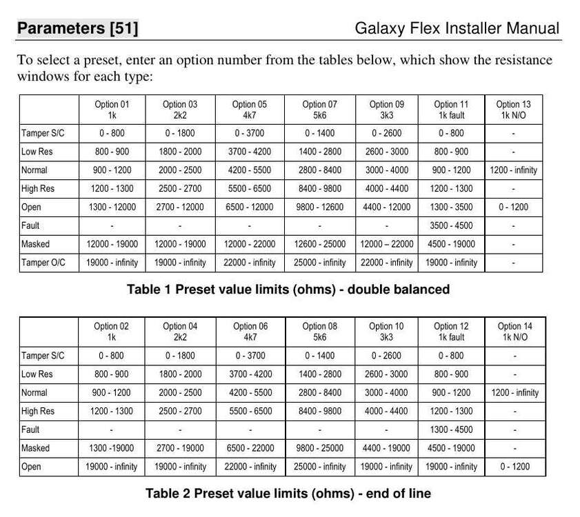
Hi Guys... did some reading in the manual, and found you can select end-of-line or double-balanced zone resistance types. Here's the table from the manual... The manual also states... When a preset is selected it sets the zone resistance range used by every zone on the system. Each zone on the system can be further customised to a specific preset by using the Resistance Select option. Now I just need to figure out which option to use ?

