I'm trying to work out the wiring of an ancient PIR sensor that's been disabled. I don't know if it's been disabled because it's faulty or for another reason.
I've got a replacement PIR sensor but I thought it would be good to work out the wiring and test the existing sensor before attempting to replace it.
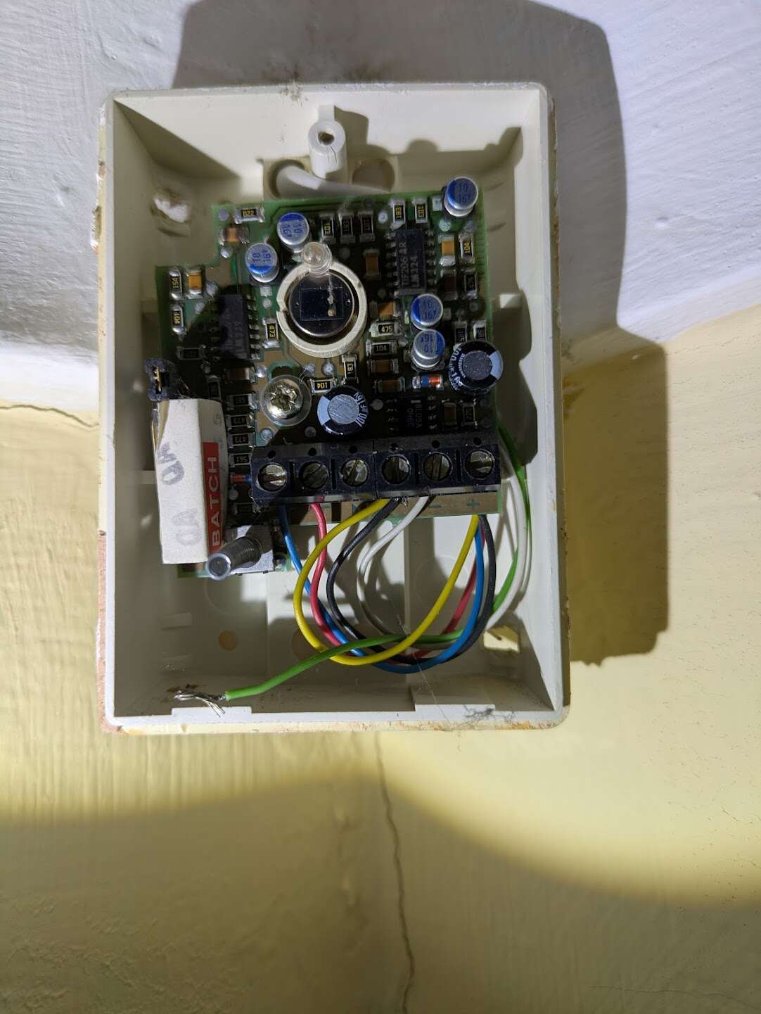
It's currently wired like this:
Blue & Red: tamper detection (T2 & T1). This is working.
Yellow & Black: Wired together in (C)
White: Negative (V-)
I guessed that Green might be V+ and the PIR circuit wired together, so I tried wiring Green to V+ and Yellow to the unused NC. This resulted in the PIR LED always being on and triggering the alarm.
I also tried Black to V+ and Green to NC, which resulted in no PIR led but always triggering the alarm.
Can anyone help?